<< Previous || Index || Next >>
Power Supplies
Orient the Jaguar version 0.6-alpha board so that the U6 (MPX4250AC6U) silk screen is located to the left side and U3 will be in the upper left corner. You should not see any of the SMD components, they should be on the back side of the board. For the remainder of the assembly manual this will be how the Jaguar board should be oriented to install the through hole components.
Install MCU Power Supply components
Step 7 :
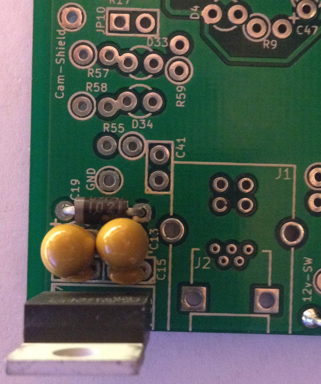
- U3 (LM2940ET-5.0) Install this component from the Through Hole side with the heatsink facing away from the center of the board.
- C15 (0.1µF)
- C17 (0.1µF)
- C13 (10µF) Polarised tantalum capacitor; Make sure that it is oriented so that the positive lead is towards the bottom of the board.
- C19 (47µF) Polarised tantalum capacitor; Make sure that it is oriented so that the positive lead is towards the top of the board.
- D3 (Not Applicable) This component is NOT required.
- D44 (1N5818-TP) Direction dependant, orient the K lead to the top edge of the board. This is indicated by the white line.
Test MCU Power Supply
Step 8 :
- Connect 12v supply positive (+) to the pad labeled 12v-SW between D44 and U6.
- Connect 12v supply negative (-) to the pad labeled GND between D3 an R55.
- Set your DMM to measure 20v DC.
- Connect the negative (-) lead from your DMM to the ground lead from your 12v supply.
- Connect the positive (+) lead from your DMM to the square pad at JP10, located between D33 and R17.
- You should read +5v DC (+/- 0.10v), if it does then the MCU Power Supply has passed this check.
- Turn off the 12v supply and disconnect your leads.
- If your MCU Power Supply has passed this test you may now jumper JP10 to supply power to the MCU.
Install Analog Sensors Power Supply components
Step 9 :
- U2 (LM2940ET-5.0) Install this component from the Through Hole side with the heatsink facing away from the center of the board.
- C14 (0.1µF)
- C16 (0.1µF)
- C12 (10µF) Polarised tantalum capacitor; Make sure that it is oriented so that the positive lead is towards the bottom of the board.
- C18 (47µF) Polarised tantalum capacitor; Make sure that it is oriented so that the positive lead is towards the top of the board.
- D43 (1N5818-TP) Direction dependant, orient the K lead to the bottom edge of the board. This is indicated by the white line.
- D2 (1N5919BG) Direction dependant, orient the K lead to the top edge of the board. This is indicated by the white line.
- MOV1 (ERZ-V14D220)
Test Analog Sensors Power Supply
Step 10 :
- Connect 12v supply positive (+) to the pad labeled 12v-SW between D44 and U6.
- Connect 12v supply negative (-) to the pad labeled GND between D3 an R55.
- Set your DMM to measure 20v DC.
- Connect the negative (-) lead from your DMM to the ground lead from your 12v supply.
- Connect the positive (+) lead from your DMM to the square pad at JP9, located between C18 and D2.
- You should read +5v DC (+/- 0.10v), if you do then your Analog Sensors power supply has passed this check.
- Turn off the 12v supply and disconnect your leads.
- If your Analog Sensors power supply has passed this test you may now jumper JP9 to supply power to the rest of the board.
Over-Voltage Protection
Turn the Jaguar version 0.6-alpha PCB over and orient the board so that the U12 (TC442xA) silk screen is located in the upper left corner. You should see all of the SMD components, they should be on the this side of the board.
Install Over-Voltage Protection components
Step 11 :
- Ux (xxx) Install this component on the SMD side with the dual pins facing the top of the board.
- Rxx (xxx ohm)
- Rxx (xxx ohm)
- Rxx (xxx ohm)
- Rxx (xxx ohm)
- Q12 (xxx) Install this component on the SMD side with the xxx pins facing the xxx of the board.
- F1 (xxx)
Test Over-Voltage Protection components
Step 12 :
- Connect 12v supply positive (+) to the pad labeled 12v-SW between D44 and U6.
- Connect 12v supply negative (-) to the pad labeled GND between D3 an R55.
- Set your DMM to measure 20v DC.
- Connect the negative (-) lead from your first DMM to the ground lead from your 12v supply.
- Connect the positive (+) lead from your first DMM to the round pad labeled 5v in the MAP section.
- Connect the negative (-) lead from your second DMM to the ground lead from your 12v supply.
- Connect the positive (+) lead from your second DMM to the round pad labeled TPS-5v near the bottom right section of the board.
- Both of your DMMs should read +5v DC (+/- 0.10v), if it does then check to make sure that Q12 or the Analog-5v regulator U2 is not overheating.
- Next the connect the TPS-5v pad to a 12v power supply and ensure that your first DMM does not read over 5.25v. Also note if Q12 overheats.
- Turn off the 12v supply and disconnect your leads.
<< Previous || Index || Next >>
